ECE 356 Computer Network Architecture: Lab 3 RIP - Routing Information Protocol
Attention
This assignment is based on your lab2 code. You should make sure that your lab2 code works well before starting this assignment;
Introduction
The goal of this assignment is to develop a simple dynamic routing protocol, RIP, so that your router can generate its forwarding table automatically based on routes advertised by other routers on the network. By the end of this project, your router is expected to be able to build its forwarding table, and route traffic through complex topologies containing multiple nodes.
Collaboration Policy
You should finish this assignment in a group of up to 2 persons.
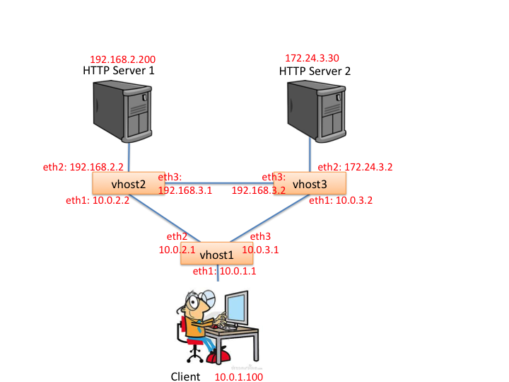
Topology and Requirements Overview
The topology of RIP is as follows. There are three routers inter-connected with each other. Client connects to the network through vhost1; Server1 connects to the network through vhost2; Server2 connects to the network through vhost3.
Your task is to implement RIP within your router so that your router will be able to do the following:
- 1. Build the correct forwarding tables on the assignment topology
- 2. Detect when routers join/or leave the topology and correct the forwarding tables correctly
Get Started
First, you should download the project here and extract it to the virtual machine. Then, run the config file with the following command:
./config.sh
Then, you can start mininet emulation by using the following command
./run_mininet.sh
You should be able to see some output like the following:
*** Shutting down stale SimpleHTTPServers
*** Shutting down stale webservers
server1 192.168.2.200
server2 172.24.3.30
client 10.0.1.100
vhost1-eth1 10.0.1.1
vhost1-eth2 10.0.2.1
vhost1-eth3 10.0.3.1
vhost2-eth1 10.0.2.2
vhost2-eth2 192.168.2.2
vhost2-eth3 192.168.3.1
vhost3-eth1 10.0.3.2
vhost3-eth2 172.24.3.2
vhost3-eth3 192.168.3.2
*** Successfully loaded ip settings for hosts
 {'vhost1-eth2': '10.0.2.1', 'vhost1-eth3': '10.0.3.1', 'server2': '172.24.3.30', 'server1': '192.168.2.200', 'vhost3-eth3': '192.168.3.2', 'vhost3-eth1': '10.0.3.2', 'vhost3-eth2': '172.24.3.2', 'client': '10.0.1.100', 'vhost2-eth3': '192.168.3.1', 'vhost2-eth2': '192.168.2.2', 'vhost2-eth1': '10.0.2.2', 'vhost1-eth1': '10.0.1.1'}
*** Creating network
*** Creating network
*** Adding controller
*** Adding hosts:
client server1 server2
*** Adding switches:
vhost1 vhost2 vhost3
*** Adding links:
(client, vhost1) (server1, vhost2) (server2, vhost3) (vhost1, vhost2) (vhost1, vhost3) (vhost2, vhost3)
*** Configuring hosts
client server1 server2
*** Starting controller
*** Starting 3 switches
vhost1 vhost2 vhost3
*** setting default gateway of host server1
server1 192.168.2.2
*** setting default gateway of host server2
server2 172.24.3.2
*** setting default gateway of host client
client 10.0.1.1
*** Starting SimpleHTTPServer on host server1
*** Starting SimpleHTTPServer on host server2
*** Starting CLI:
mininet>
Then, start the Mininet controller (and wait for it to print some messages)
./run_pox.sh
It will print messages that look like this:
POX 0.5.0 (eel) / Copyright 2011-2014 James McCauley, et al.
server1 192.168.2.200
server2 172.24.3.30
client 10.0.1.100
vhost1-eth1 10.0.1.1
vhost1-eth2 10.0.2.1
vhost1-eth3 10.0.3.1
vhost2-eth1 10.0.2.2
vhost2-eth2 192.168.2.2
vhost2-eth3 192.168.3.1
vhost3-eth1 10.0.3.2
vhost3-eth2 172.24.3.2
vhost3-eth3 192.168.3.2
INFO:.home.ubuntu.projects.pwospf.pox_module.pwospf.srhandler:created server
INFO:core:POX 0.5.0 (eel) is up.
INFO:openflow.of_01:[00-00-00-00-00-01 1] connected
{'vhost1': {'eth3': ('10.0.3.1', '6e:63:7a:c1:8f:a5', '10Gbps', 3)}}
{'vhost1': {'eth3': ('10.0.3.1', '6e:63:7a:c1:8f:a5', '10Gbps', 3), 'eth2': ('10.0.2.1', '16:14:f7:e0:85:e0', '10Gbps', 2)}}
{'vhost1': {'eth3': ('10.0.3.1', '6e:63:7a:c1:8f:a5', '10Gbps', 3), 'eth2': ('10.0.2.1', '16:14:f7:e0:85:e0', '10Gbps', 2), 'eth1': ('10.0.1.1', '7a:34:84:7b:9c:f1', '10Gbps', 1)}}
INFO:openflow.of_01:[00-00-00-00-00-03 3] connected
{'vhost3': {'eth3': ('192.168.3.2', '6e:b3:50:d4:0e:88', '10Gbps', 3)}}
{'vhost3': {'eth3': ('192.168.3.2', '6e:b3:50:d4:0e:88', '10Gbps', 3), 'eth2': ('172.24.3.2', '16:06:70:9f:57:da', '10Gbps', 2)}}
{'vhost3': {'eth3': ('192.168.3.2', '6e:b3:50:d4:0e:88', '10Gbps', 3), 'eth2': ('172.24.3.2', '16:06:70:9f:57:da', '10Gbps', 2), 'eth1': ('10.0.3.2', '72:01:bd:a5:f4:af', '10Gbps', 1)}}
INFO:openflow.of_01:[00-00-00-00-00-02 2] connected
{'vhost2': {'eth3': ('192.168.3.1', 'ae:be:9f:e7:15:00', '10Gbps', 3)}}
{'vhost2': {'eth3': ('192.168.3.1', 'ae:be:9f:e7:15:00', '10Gbps', 3), 'eth2': ('192.168.2.2', '56:7a:50:a1:9e:bb', '10Gbps', 2)}}
{'vhost2': {'eth3': ('192.168.3.1', 'ae:be:9f:e7:15:00', '10Gbps', 3), 'eth2': ('192.168.2.2', '56:7a:50:a1:9e:bb', '10Gbps', 2), 'eth1': ('10.0.2.2', 'de:17:8f:8c:4d:19', '10Gbps', 1)}}
Then, you can start the reference solution now.
Since there are 3 routers in this assignment's topology, we need to run the binary file for 3 times.
You should use the following command to run the reference soultion
./sr_solution -t 300 -s 127.0.0.1 -p 8888 -v vhost1
./sr_solution -t 300 -s 127.0.0.1 -p 8888 -v vhost2
./sr_solution -t 300 -s 127.0.0.1 -p 8888 -v vhost3
For each reference solution, e.g. vhost1, you will see the following output
ubuntu@ubuntu-VirtualBox:~/projects/pwospf/pwospf_stub$ ./sr -t 300 -s 127.0.0.1 -p 8888 -v vhost1
Using VNS sr stub code revised 2009-10-14 (rev 0.20)
Client ubuntu connecting to Server 127.0.0.1:8888
Requesting topology 300
successfully authenticated as ubuntu
Router interfaces:
eth3	HWaddrde:a4:7b:c8:92:5c
    inet addr 10.0.3.1
    inet mask 255.255.255.252
eth2	HWaddrce:10:da:1f:4e:84
    inet addr 10.0.2.1
    inet mask 255.255.255.252
eth1	HWaddrca:b8:a7:51:e2:ea
    inet addr 10.0.1.1
    inet mask 255.255.255.0
    <---------- Router Table ---------->
Destination	Gateway		Mask		Iface	Metric	Update_Time
10.0.3.0	0.0.0.0	255.255.255.252	eth3	0	09:19:12
10.0.2.0	0.0.0.0	255.255.255.252	eth2	0	09:19:12
10.0.1.0	0.0.0.0	255.255.255.0	eth1	0	09:19:12
    <-- Ready to process packets -->
When you run 2 or more reference solutions, these reference solutions will automatically start exchanging the routing information.
You will see the following updating in each 5 seconds in each reference solution. The following routing table is for vhost1.
<---------- Router Table ---------->
Destination	Gateway		Mask		Iface	Metric	Update_Time
10.0.3.0	0.0.0.0	255.255.255.252	eth3	0	09:20:49
10.0.2.0	0.0.0.0	255.255.255.252	eth2	0	09:20:46
10.0.1.0	0.0.0.0	255.255.255.0	eth1	0	09:20:47
192.168.3.0	10.0.3.2	255.255.255.252	eth3	1	09:20:49
172.24.3.0	10.0.3.2	255.255.255.0	eth3	1	09:20:49
192.168.2.0	10.0.2.2	255.255.255.0	eth2	1	09:20:46
After the routing table converges, you can input some commands to the mininet terminal to test this reference solution.
You can use traceroute to see the route between client to server1.
mininet> client traceroute -n 192.168.2.200
You should be able to see the following output.
traceroute to 192.168.2.200 (192.168.2.200), 30 hops max, 60 byte packets
1  10.0.1.1  83.931 ms  83.908 ms  46.873 ms
2  10.0.2.2  172.296 ms  172.467 ms  172.608 ms
3  192.168.2.200  372.283 ms  372.491 ms  331.607 ms
You can also use this command to block the link between vhost1 and vhost2
link vhost1 vhost2 down
Then, you should wait routing table converges. It will take 1 - 2 minutes.
The vhost1's routing table will be the following result after the link vhost1-vhost2 blocked.
Destination	Gateway		Mask		Iface	Metric	Update_Time
10.0.3.0	0.0.0.0	255.255.255.252	eth3	0	05:15:56
10.0.1.0	0.0.0.0	255.255.255.0	eth1	0	05:11:25
172.24.3.0	10.0.3.2	255.255.255.0	eth3	1	05:15:56
192.168.3.0	10.0.3.2	255.255.255.252	eth3	1	05:15:56
192.168.2.0	10.0.3.2	255.255.255.0	eth3	2	05:15:56
If you input the traceroute command again, you will see the different result.
mininet> client traceroute -n 192.168.2.200
traceroute to 192.168.2.200 (192.168.2.200), 30 hops max, 60 byte packets
    1  10.0.1.1  69.843 ms  69.878 ms  109.743 ms
    2  10.0.3.2  302.315 ms  302.266 ms  302.762 ms
    3  192.168.3.1  413.774 ms  418.776 ms  413.808 ms
    4  192.168.2.200  505.606 ms  505.666 ms  457.865 ms
You can also use the following command to cover a blocked link
link vhost1 vhost2 up
If the link is fixed, the result of the traceroute will also be fixed.
I will use these testcases to grade your code.
Protocols to Understand
User Datagram Protocol
To further understand UDP, you can read the RFC768. In this assignment, we provide the struct for UDP header
struct sr_udp_hdr {
    uint16_t port_src, port_dst; /* source and destination port_number */
    uint16_t udp_len;			/* total length */
    uint16_t udp_sum;			/* checksum */
    } __attribute__ ((packed)) ;
    typedef struct sr_udp_hdr sr_udp_hdr_t;
You need to set the port number as well as the UDP length. You should also set the correct checksum for UDP header.The default source and destination port_number for Routing Information Protocol are both 520.
Routing Information Protocol
In this assignment, we use RIPv2 to exchange routing information. You can read RFC2453 for more details.We also provide the struct for RIP packets
struct sr_rip_pkt {
    uint8_t command;
    uint8_t version;
    uint16_t unused;
    struct entry{
        uint16_t afi; /* Address Family Identifier */
        uint16_t tag; /*Route Tag */
        uint32_t address; /* IP Address */
        uint32_t mask; /* Subnet Mask */
        uint32_t next_hop; /* Next Hop */
        uint32_t metric; /* Metric */
        } entries[MAX_NUM_ENTRIES]; /* #define MAX_NUM_ENTRIES 25 */
    } __attribute__ ((packed)) ;
    typedef struct sr_rip_pkt sr_rip_pkt_t;
You should send both RIP request and RIP response packets and using these packets to update your routing table;
Code Overview
In this assignment, you should implement the following functions:
void sr_handlepacket(struct sr_instance* sr, uint8_t * packet, unsigned int len, char* interface) -  sr_router.c
void sr_arpcache_sweepreqs(struct sr_instance *sr) - sr_arpcache.c
This two functions are already implemented by yourselves in lab2. For the lab3, you need to also add the function to handle RIP packets.
Notice: We have changed the struct for the interface and router table, maybe your lab2 code need to be a little modified according to our changes.
void *sr_rip_timeout(void *sr_ptr); - sr_rt.c
This function is defined in sr_rt.c and called every 5 seconds, to send the RIP response packets periodically. It should also check the routing table and remove expired route entry. If a route entry is not updated in 20 seconds, we will think it is expired.
void send_rip_request(struct sr_instance *sr); - sr_rt.c
This function is defined in sr_rt.c. You should send RIP request packets using UDP broadcast here. This function is called when the program started. The router who will receive a RIP request packet will send a RIP reponse immediately.
void send_rip_response(struct sr_instance *sr); - sr_rt.c
This function is defined in sr_rt.c. You should call it when you receive a RIP request packet or in the sr_rip_timeout function. You should enable split horizon here to prevent count-to-infinity problem.
void update_route_table(struct sr_instance *sr, sr_ip_hdr_t* ip_packet, sr_rip_pkt_t* rip_packet, char* iface); - sr_rt.c
This function is defined in sr_rt.c and will be called after receiving a RIP response packet. You should enable triggered updates here. When the routing table changes, the router will send a RIP response immediately.
Notice
When you type the command to block a link, for example:
link vhost1 vhost2 down
The mininet will change the vhost1-eth1's and vhots2-eth1's interfaces status from up to down, so that these two interfaces cannot send and receive packets any more. you can use the following command to do the same thing:
vhost1 ifconfig vhost-eth1 down
When an interface's status changed, this information will send directly to your program. You can call the following function to obtain the status of an interface in your code:
uint32_t sr_obtain_interface_status(struct sr_instance* sr, const char* name)
How to Submit
Go to the router folder, create a file named "README" with your group members' names, and
make submit
Upload the compressed file on Canvas.
Acknowledgement
We thank the course staff of CS344 at Stanford University for their support. This lab is adapted from one of their assignments. You can visit their Wiki page here.